Standard 1-D collimation geometry
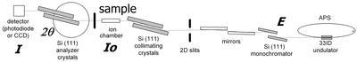
The beam goes from the right (APS synchrotron) to left (detector). It passes through the monochromator (double bounce Si 111), two mirrors for harmonic energy rejection, and through the beam defining slits. There the USAXS instrument starts: the beam passes through Si 220 channel-cut, note the figures are obsolete, ( 4 reflections), ion chamber (intensity monitor) and sample. After sample the scattered beam is analyzed by second (rotating) Si (220) channel-cut crystal (4 reflections) and measured by photodiode. Both analyzing channel-cut and photodiode are moved vertically as the analyzing channel-cut is rotated. This extends the measurable Q to range normally not available on these types of instruments.
The photodiode detector is linear over at least 9 decades of intensity. This photodiode can be replaced by CCD camera for imaging - radiography. This allows users to locate the sample – and locate are of interest – with high precision (about 10 mm).
2-D collimation (side-bounce) geometry
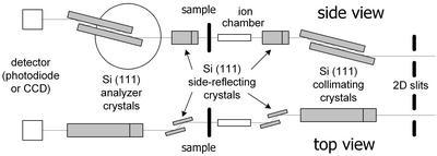
In this setup two side reflection stages (Si 220 channel-cuts) are added – one before the ion chamber and one after the sample. These channel-cuts define the beam in the horizontal direction, effectively removing the slit smearing. This comes at a cost of some loss of intensity and Q range, therefore this configuration is appropriate only in selected cases – especially for anisotropic samples where small Q range and high Q resolution are needed – basically with for anisotropic samples with large scatterers…